Connecting Sensors to Data Acquisition System Analog Inputs
June 05, 2015 -
"White Papers"
Properly connecting sensors to a data acquisition system is as crucial as selecting the proper sensor for the application, and there are multiple factors that need to be taken into consideration to ensure that stable measurements are acquired with minimal noise and effect on other components connected to the system.
This white paper discusses the recommended methods for connecting sensors and/or external signals to +/-10V analog inputs that are provided on data acquisition systems for end user connection. A sensor that is wired to a system incorrectly can not only cause inaccurate measurements on that channel, it could possibly introduce problems on other channels including channels that had been working correctly previously.
The following simplified schematic is representative of a single analog input connection provided in a Wineman Technology data acquisition system, and will be used as the basis for this paper. The analog input is configured as differential and is typical of that found on many of the National Instruments data acquisition modules across the PC, PXI, NI CompactDAQ, and CompactRIO platforms.

Terminals or a bulkhead connector will be provided in a typical Wineman Technology design data acquisition system for connecting external sensors and will include the following connections:
| Terminal | Description |
| EXC+ | Excitation Power |
| EXC- | Excitation Common |
| SIG+ | Signal Positive |
| SIG- | Signal Negative |
| SHIELD | Shield |
One common misconception is that an analog input on a data acquisition system is similar to a digital multimeter (DMM). There have been cases where a sensor will read correctly with a DMM yet will not provide valid readings on a data acquisition system. Although an analog input appears to be like a DMM measuring voltage, it is not intended for measuring floating signals. Most data acquisition modules require that the signal have a common mode voltage of
Connecting 4-Wire Sensors
Many of the sensors commonly used for data acquisition provide a 4-wire connection. The types of sensors that fall into this category include conditioned bridge-type transducers, such as pressure transducers, load cells, and torque transducers. For the purpose of this example, we will focus on strain-type devices; however the principals outlined below also apply to other sensor types. Many manufacturers of strain-type sensors provide options for including integrated signal conditioning in the sensor since it delivers a linearized, high-level signal (+/-10V typically) to the data acquisition system, as opposed to providing signals at or below 50mV. Noise induced on higher-level signals will be less significant than if induced on a low-level signal.
The following schematic provides the recommended wiring for connecting a 4-wire sensor to a data acquisition system.

Connecting 3-Wire Sensors
Some sensors are provided with 3-wire connections and may include OEM-type pressure transducers as well as potentiometers. Connecting a 3-wire sensor to a data acquisition system is similar to the method used for connecting a 4-wire sensor, except the negative signal will be tied to the excitation common at the sensor.

It is possible to wire a 3-wire sensor to the data acquisition system using a 3-conductor shielded cable and providing a jumper at the terminal between EXC- and SIG- but the signal will be more susceptible to noise since it is not being transmitted on a differential pair.

Connecting a Current Loop Sensor
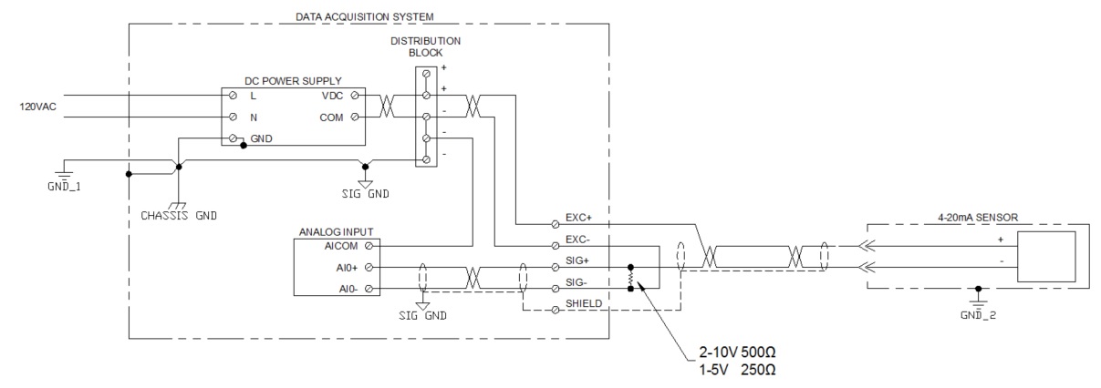
Transducers powered by current loops are also used on data acquisition systems and can be wired into a voltage analog input easily by adding a pull-down resistor (as shown below). Typically 500? resistors are used to create a 10V drop across the analog input, though 250? resistors can be used for creating a 5V drop instead. Any value of resistor can be used as long as it does not create more than a 10V drop at the full-scale output of the sensor. It is best practice to use either a high-precision metal film or wire-wound resistor to provide an accurate, stable resistance with minimal drift.
Connecting a Floating Sensor
When it is necessary to connect a floating sensor to an analog input on a data acquisition system, a 1M? bias resistor will need to be installed in order to ensure that the signal is within the common-mode voltage range of the analog input. The resistor will provide the necessary reference while minimizing the current induced by connecting the two circuits.
The following schematic provides an example of how to connect a battery-powered sensor to a data acquisition system. There are special cases when the sensor is a device powered by a separate circuit (i.e., the speed feedback from a variable frequency drive) where it would be best to install a signal isolator between the two circuits (this is covered in the next section).

Terminating Shields
There are three basic rules that should always be followed when terminating shields, though they frequently are overlooked.
The shield should be connected to the zero-signal reference potential of the signal contained within the cable.
The shield should be connected to the zero-signal reference potential at the signal-earth connection.
The shield should only be terminated at one end.
As the cable increases in length between a data acquisition system and a sensor, the importance of terminating the shield properly increases. A properly terminated shield will create a low-pass filter that will become a high-pass filter if terminated at the other end.
There are special cases where shields are terminated at both ends; however, this should be avoided as it introduces the chance of inducing current through the shield. This may happen due to potential differences between the ground planes at either end, creating what is commonly referred to as a ground loop.
Cable Selection
For optimal system performance, all sensors need to be connected to the data acquisition system using shielded twisted pair cabling. The shield, when properly terminated, will minimize voltage induced by outside electromagnetic sources which may include electric power transmission lines, load switching, fluorescent lighting, and/or radio signals. A twisted pair will cause any induced noise to be generated equally on both signal lines so that it can be eliminated by a differential analog input.
When installing shielded twisted pair cabling, it is recommended that the length of exposed, unshielded wire be minimized to a length not exceeding 4” when terminated inside the data acquisition enclosure, and 2” if terminated outside the enclosure.
There are a wide variety of vendors that provide twisted shielded cables intended for use in data acquisition systems. When selecting cable, it is preferred that each twisted pair be individually shielded in order to minimize any capacitive coupling between the excitation power and the measured signal. The following is a sample of some of the cables used by Wineman Technology when designing and building a data acquisition system.

Belden 8723 Two Twisted Shielded Pair Cable with PVC Jacket

Belden 8451 One Twisted

Shielded Pair Cable with PVC Jacket
While wiring sensors to systems may seem mundane, research and planning can ensure a properly functioning system and can help avoid costly problems later in the project. There are many other wiring considerations that we didn’t cover in this article; however, we are confident that the practices discussed above will help you on your next application. If you need additional help please do not hesitate to contact us at winemantech.com/contact.

 Castings & Forgings
 Bulk Material Handling
 Electrical & Electronic Components
 Flow Instrumentation
 Hardware
 Material Handling Equipment
 Metal Cutting Services
 Metal Forming Services
 Metal Suppliers
 Motion Control Products
 Plant & Facility Equipment
 Plant & Facility Supplies
 Plastic Molding Processes
 Pumps & Valves
 Recycling Equipment
 Rubber Products & Services